|
Adjust-A-Gate - Non-Sag Steel Frame Kit for Wood and Vinyl Gates
|
|
| |
Adjust-A-Gate Installation
Instructions |
|
| Note: The gate
you build will be approximately 2" shorter width than your gate opening size to allow
room for hinges and latch. Maximum width of gate kits is actually 58" (AG36) and 94" (AG60). |
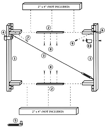
PARTS LIST - Model: AG36/AG60
| # |
Qty |
Part Name |
| 1 |
2 |
1-1/2" x 1-1/2" x
45" Vertical Members |
| 2 |
2 |
1" X 1" X 26" Inside Slip Members
(or 1" x 1" x 48" for AG60) |
| 3 |
1 |
Truss Cable Kit |
| 4 |
2 |
Gate Frame Hinges |
| 5 |
2 |
Wood Post Hinges |
| 6 |
1 |
Gate Latch |
| 7 |
12 |
1" Wood Screws |
| 8 |
6 |
3" Wood Screws |
| 9 |
2 |
Tek Screws |
| 10 |
4 |
2" x 1/4" Self Drilling Screws (not
shown) |
| 11 |
1 |
Gate Stop Kit |
| TOOLS NEEDED: |
- 9/32" Wrench or Adjustable End Wrench
- 7/16" Wrench or Adjustable End Wrench
- 9/16" Wrench or Adjustable End Wrench
- Phillips Screw Driver
- Wire Cutters
- Drill Motor
- 1/2" Spade Drill Kit
|
|
 |
Step 1
Installing Post Hinges
 |
Step One
Installing Post Hinges
The Adjust-A-Gate™ is made to swing in. With this in mind you
will want to locate your hinges toward the back edge of the gate post so the latch will
work properly.
- Locate the center point between your top and bottom rails.
- Measure up and down approximately 16" (20" for 3-rail) and
make a mark 1" from the back edge of your post
- Using a 1/2" spade bit, drill a pilot hole for the lag hinges.
- Using pliers or a wrench, screw the lag hinge in approximately
1" tolerance to outside of hinge pin.
|
|
Step Two
Assemble Gate Frame
 |
Step Two
Assemble Gate Frame
The Adjust-A-Gate™ can be used for 4', 5', and 6' high fences
and will adjust to virtually any opening from 36" to 60" (AG36) or 60" to
96" (AG60).
- Hang the hinge side of the Adjust-A-Gate on the post using the frame
hinges provided.
- Insert the 2 - 1" Spreader bars into the slip members on the
frame (be sure that the holes in the spreader bar are facing up and down.)
|
Step 3
Positioning
 |
Step Three
Positioning
- Slide the latch side of frame onto the spreader bars.
- Swing the gate to the closed position and adjust the frame to
approximately 1" between the frame and post.
|
Step 4
2 x 4 Installation
 |
Step Four
2 x 4 Installation
- Measure, cut, and install 2 x 4's with screws provided (7, 8) as
shown. (Depending on the width of your gate you may not need all of the long screws (8) in
the frame.)
|
Step 5
Hinges, Wire Truss Cable and Gate Stop
 |
Step Five
Hinges, Wire Truss Cable and Gate Stop Installation
- Now you can install the frame hinges (4) and hang your gate.
- Install the "S" Hook for the truss cable kit into the hole
at the top of the gate on the hinge side. Install the truss cable kit (3) by hooking the
turnbuckle into the hole at the bottom of the gate on the latch side. Use the clamp
provided to secure the cable, cut off excess. Adjust turnbuckle to mild tension.
- Install the Latch Bar to gate frame, then the Latch Keeper to the
post.
- Install Stop, using the carriage bolt and nylock nut provided.
|
Step 6
Installing Fence Boards, Adjusting Gate
 |
Step Six
Installing Fence Boards, Adjusting Gate
- Now you can install the fence boards to your specifications using
nails or screws. If you have trouble stabilizing your boards at the outside edges of the
Adjust-A-Gate™, you can use the 4 self-drilling screws (10) provided and attach the
boards directly to the gate frame.
- By adjusting the turnbuckle on the truss cable you can fine tune the
latch to give you that perfect fit.
- CONGRATULATIONS!! You have done a great job. You now have a beautiful
gate that matches your fence and looks like a custom job. Now you can look forward to
years of trouble free use.
|
|
|
Click here for
more information and online ordering. |
|
 |
|
Adjust-A-Gate - Non-Sag Steel Frame Kit for Wood and Vinyl Gates
|
All content © Hoover Fence Co. 2011
Dealer/ Distributor of Adjust-A-Gate™ products
4521 Warren Rd. - Newton Falls, Ohio 44444
(330)
358-2335 phone | (330) 358-2624 fax
www.hooverfence.com
*Adjust-A-Gate™ is a trademarked name, property of its respective
owner. |
|
|
|
|